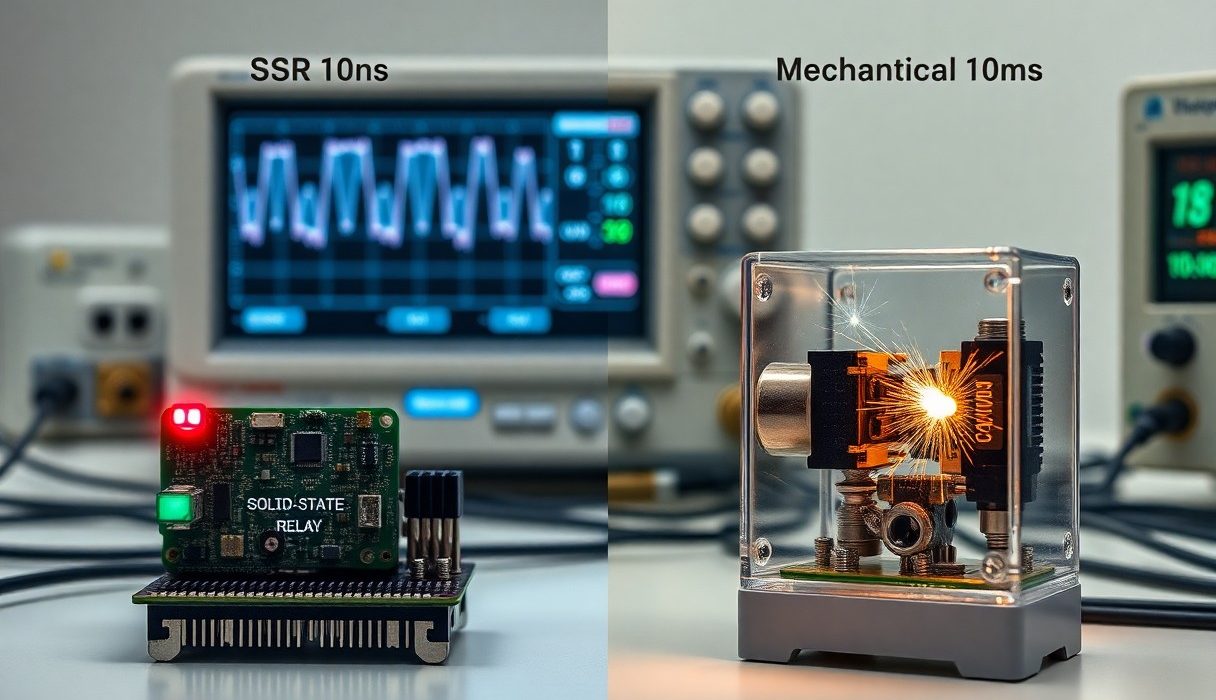
Comparison of switching speeds shows that solid-state relays (SSRs) switch in microseconds to milliseconds while mechanical relays operate in milliseconds with contact bounce; you should value SSRs for their long life and lack of contact wear but be aware SSRs can generate heat and fail short under overload, while mechanical relays risk arcing and contact degradation, so choose based on your switching frequency, load type, and thermal management.
Types of Relays
You can classify relays by their switching mechanism and intended application: some are semiconductor-based with very fast switching, while others use moving parts that provide low on-resistance and clear galvanic separation. In practice, choice depends on factors like required switching speed, load type (AC vs DC), expected lifecycle (from ~10^5 to >10^9 operations), and whether you need to handle high inrush current or suppress arcing.
Practical examples include industrial SSRs used in heater control that switch in microseconds to milliseconds but require heatsinking for dissipation, versus heavy-duty electromechanical relays (EMRs) in motor starters that tolerate tens of amps and switch in the single-digit to tens of milliseconds range but present contact bounce and arcing risks on DC loads.
| Solid State Relay (SSR) | Switching: ~µs-ms; no physical contacts; isolation up to ~4 kV; leakage current (µA-mA); lifespan >10^7 cycles |
| Electromechanical Relay (EMR) | Switching: ~5-20 ms; contact bounce 1-10 ms; ratings up to 30-100 A in industrial types; lifespan ~10^5-10^7 cycles |
| Reed Relay | Switching: ~0.5-2 ms; small currents (mA-A); low contact capacitance; life up to 10^9 cycles in low-power use |
| Latching Relay | Switching: ~5-20 ms; holds state without continuous coil power; used where power saving is needed |
| Hybrid Relay | Switching: ~1 ms; combines mechanical contacts with solid-state elements to reduce arc and improve life; niche use |
- solid state relay
- mechanical relay
- switching speed
- SSR
- EMR
Solid State Relays
You will find solid state relays achieving the highest effective switching rate because they rely on semiconductor switches (MOSFETs, IGBTs, TRIACs) rather than moving parts. Typical turn-on/turn-off can be in the microsecond to millisecond range depending on the topology; for example, MOSFET-based DC SSRs switch in tens to hundreds of microseconds while TRIAC-based AC SSRs often switch with zero-cross circuitry and therefore act in milliseconds.
When you evaluate an SSR, check on-resistance (or voltage drop), leakage current (which can be problematic for low-current loads), and thermal resistance-an SSR dissipating a few watts may need a heatsink to avoid thermal shutdown. In one field case, replacing a mechanical heater contactor with an SSR eliminated contact maintenance but required a heatsink sized for ~5 W dissipation at continuous load.
Mechanical Relays
You can count on mechanical relays to provide true galvanic isolation and very low contact resistance (milliohms), which matters when you need minimal conduction loss. Typical operate times fall in the ~5-20 ms window, with contact bounce lasting ~1-10 ms; designers commonly add debouncing in control logic or RC/snubber networks to protect downstream electronics and reduce false triggers.
Because of physical contacts, you must address arcing and contact wear if switching inductive or high-inrush loads-motors or transformer loads can produce inrush currents many times rated value and lead to contact welding. For example, a 3-phase motor starter relay may be specified for 30 A continuous but requires additional arc suppression or pre-charge circuits to survive repeated starts.
Thou should factor contact material (silver, silver‑nickel, or ruthenium), DC breaking capacity, recommended maintenance intervals, and arc-suppression methods into your selection so you avoid contact welding and ensure the relay meets your switching-speed and lifetime requirements.
Switching Speed Comparison
| Solid State Relay (SSR / Semiconductor) | Mechanical Relay |
|---|---|
| Typical switching time: sub-µs to low-µs for MOSFET/IGBT-based devices; many packaged SSRs (especially AC/zero-cross types) introduce delays up to ~5-10 ms. | Typical switching time: ~2-20 ms for electromechanical coils; actuation and contact closure are inherently in the millisecond range. |
| Contact-like behavior: no physical contacts, so no mechanical bounce; switching waveform and dv/dt depend on semiconductor and snubber network. | Contact bounce: contact bounce commonly ranges from ~100 µs up to a few ms, which you must debounce in digital circuits. |
| Lifetime (switching cycles): typically >10^7-10^9 operations (limited by thermal/stress on semiconductors). | Lifetime (switching cycles): typically 10^4-10^7 mechanical operations depending on load and contact rating. |
| On-state loss & heating: depends on Rds(on) or forward drop; can cause significant continuous dissipation and requires heatsinking in high-current applications. | On-state loss & heating: very low contact resistance (milliohms) at rated current, but switching under load can cause arcing and contact wear. |
| Best use cases: high-speed PWM, telecom switching, fast DC/logic-level switching, applications demanding long mechanical life. | Best use cases: mains power switching, isolated control of inductive loads, simple control panels where millisecond response is acceptable. |
Overview of Switching Speeds
When you need sub-microsecond or microsecond-level transitions-for example in high-frequency PWM motor drives or telecom line switching-you’ll reach for semiconductor switches because MOSFETs and IGBTs can change state in the ns-µs range under controlled drive conditions. Practical packaged SSRs, however, often impose additional latency: optical isolation, gate drive shaping, or deliberate zero-cross firing for AC models can push effective turn-on to the millisecond domain, so check the device datasheet for turn-on/turn-off times, propagation delay and specified rise/fall times.
By contrast, if your design tolerates millisecond response, mechanical relays remain viable and predictable: coil actuation plus contact closure typically totals a few milliseconds, and you must handle contact bounce (hundreds of µs to a few ms) in digital logic. In high-voltage or noisy environments, the inherent physical separation of contacts also gives you different failure modes-contact pitting and wear rather than semiconductor thermal runaway-that affect long-term switching performance.
Efficiency in Different Applications
For continuous conduction efficiency, you’ll often find SSRs introduce higher sustained losses: MOSFET-based SSRs present an Rds(on) that generates I^2R heating and may require heatsinking; TRIAC/thyristor SSRs have a significant forward voltage drop (often >1 V) that becomes multiple watts at tens of amps. Mechanical contacts typically have <1-10 mΩ resistance when new, so your steady-state conduction loss can be lower and cooling requirements smaller for the same current level.
On the other hand, SSRs let you switch at much higher frequencies without mechanical wear, which can improve system-level efficiency in applications like soft-starts or active power management where you reduce losses elsewhere by fast switching. You must also factor in off-state leakage: many SSRs leak milliamps when “off,” which can be dangerous for low-current circuits or create standby losses in battery-powered systems, whereas mechanical relays provide near-zero leakage when open.
In inductive or high-inrush scenarios you should evaluate transient behavior: SSRs can produce large dv/dt and require snubbers or controlled slew to avoid EMI or device stress, while mechanical relays may arc during switching and suffer rapid contact deterioration under repeated heavy switching. If your system must handle repeated high inrush currents or switch mains frequently, you’ll need to balance SSR thermal design against mechanical contact lifetime and maintenance costs.
Factors Affecting Switching Speed
Several physical and electrical parameters directly influence switching speed and the observable differences between solid state and mechanical relays: coil/drive dynamics, contact physics, load characteristics, and environmental stresses. You will see mechanical operate times typically in the 5-20 ms range with contact bounce adding 1-5 ms of effective chatter, whereas many solid state devices switch in microseconds to low milliseconds (for example, MOSFET-based SSRs can commutate in hundreds of nanoseconds, while TRIAC/thyristor SSRs used for AC zero-cross have effective switching tied to the mains crossing and so appear slower). A practical design checklist helps prioritize which parameter to optimize:
- Load Type – resistive, inductive, or capacitive loads dictate arc energy and inrush behavior.
- Voltage & Current – higher rms or peak values increase arc persistence and energy to be managed.
- Drive Voltage / Gate Charge – determines how fast a semiconductor can transition; low gate drive slows MOSFETs even if device rated fast.
- Contact Material & Design – silver alloys, tungsten, plated contacts change bounce, weld tendency, and life.
- Ambient Conditions – temperature, humidity, altitude, and vibration alter both speed and reliability.
- Mechanical Wear – contact erosion and spring fatigue increase operate times and variability over cycles.
Load Type
If you switch predominantly inductive loads (motors, solenoids, transformers), expect slower effective interruption and higher arc energy than with pure resistive loads. For example, a small 1/2 HP AC motor can produce inrush currents 6-8× its running current during start-up; that spike both lengthens the arcing period on contact opening and raises the chance of contact welding. In practice you’ll need snubbers, TVS diodes, or RC networks for inductive loads, and you should specify relays with higher make/break ratings than the steady-state values – a relay rated for 10 A resistive might need to be rated for 50-80 A inrush handling if used on motor loads.
When you consider capacitive or lamp loads, note that initial charging currents and cold-filament inrush can be similarly punitive: an incandescent or LED driver input cap can draw 10-20× steady current momentarily. Solid state relays can avoid contact bounce and handle repetitive high-frequency switching for duty cycles, but they present leakage current and may not be suitable where true open-circuit isolation is required; conversely, mechanical types provide galvanic isolation yet suffer from bounce and limited switching frequency (typically under 5-10 operations per second continuous for general-purpose relays).
Ambient Conditions
Temperature has a direct, measurable impact: you’ll find MOSFET-based SSRs with Rds(on) that can rise by tens of percent as junction temperature moves from 25 °C to 100 °C, slowing thermal recovery and increasing conduction losses – which in turn forces thermal derating and can change effective switching timing under load. For mechanical relays, coil viscosity and spring dynamics slow actuation at low temperatures and accelerate contact wear at high temperatures; many commercial relays are specified from −40 °C to +85 °C, and performance near the extremes will deviate from room-temperature data.
Humidity and contamination produce another class of effects: you should expect increased contact resistance and intermittent chatter in high-humidity or salt-laden environments unless you use sealed or hermetic relays. Vibration and shock will exaggerate contact bounce and may force premature closures or openings – in field tests, relays in high-vibration enclosures showed bounce durations increase by 30-50% compared with bench conditions. Altitude also matters because dielectric breakdown threshold drops as pressure falls, making arcing more probable at high elevation when switching high voltages.
To manage these effects you should derate or select relays with explicit environmental specs, apply snubbers or suppression networks, and provide thermal/motion control for high-frequency switching; sealed relays or conformal coatings mitigate humidity effects, while heatsinking and forced air are standard for SSRs switching more than a few watts at kilohertz rates. Thou must size components for the worst-case ambient and switching scenario to avoid premature failure.
Pros and Cons of Solid State Relays
| Pros | Cons |
|---|---|
| Very fast switching: MOSFET/IGBT SSRs can switch in microseconds to hundreds of microseconds, enabling PWM and high-frequency control. | Off-state leakage: many SSRs have milliamp-level leakage (commonly 1-5 mA for triac-based SSRs) that can leave loads partially energized. |
| Extremely long life: no moving parts yields lifetimes often >10^7-10^9 cycles vs mechanical relays’ ~10^5-10^7 cycles. | Thermal dissipation: on-state voltage drop or RDS(on) causes continuous heat; e.g., 10 A through 0.1 Ω = 10 W to dissipate. |
| Silent, bounce-free switching and precise timing – ideal for automated, high-speed systems and repeatable control. | Failure modes: SSRs tend to fail short, which can be more dangerous than the open failures common to mechanical relays. |
| Compact and low-maintenance; opto-isolation gives isolation ratings typically in the kilovolt range for control-to-load. | Not ideal for all AC controls: triac zero-cross SSRs cannot perform phase-angle dimming or arbitrary phase switching. |
| Low control drive current – many SSRs interface directly to logic-level signals or low-current drivers. | Limited surge/inrush handling compared with contacts; you must verify peak and repetitive surge ratings for motors or lamps. |
| No arcing or contact wear, making SSRs preferable in dusty or explosive atmospheres where sparks are unacceptable. | EMI and dv/dt sensitivity: fast edges and snubber networks may be required for inductive loads. |
| Repeatable and predictable on/off timing useful for PID or burst-fire control of heaters and industrial processes. | Higher static power loss for high-current DC switching than an equivalent low-resistance contact – impacts efficiency. |
| Commonly used in industry for resistive loads (ovens, heaters), instrumentation switching, and solid-state contactors. | Some SSR types lack true galvanic isolation between load poles (depends on design), so careful selection is needed for safety-critical circuits. |
Advantages
You gain sub-millisecond to microsecond switching capability with MOSFET- or IGBT-based SSRs, which lets you implement high-frequency PWM or precise timing for temperature control and fast actuation. In practice, industrial heater control often uses SSRs to burst-fire whole AC cycles (cycle control) with much higher repeatability than mechanical relays, and laboratories use MOSFET SSRs to switch DC loads at tens of kilohertz for power electronics experiments.
Maintenance overhead drops because there are no contacts to wear or arc. For long-run automated systems you will see lifetimes measured in tens to hundreds of millions of operations, and the silent operation plus opto-isolation (isolation ratings commonly in the kilovolt range) simplifies layout and lowers electromagnetic interference in measurement chains.
Disadvantages
You must plan for off-state leakage – many SSRs allow small currents when “off,” which can keep indicator lamps glowing or allow heaters to warm slightly. Also consider that triac/thyristor-style SSRs typically implement zero-cross switching, so they cannot perform phase-angle control and depend on mains frequency for turn-off timing (half-cycle behavior of ~8.3 ms at 60 Hz or 10 ms at 50 Hz).
Thermal management is another area where you will need to design carefully: semiconductor on-state drop produces continuous dissipation (P = I^2·RDS(on) or Vdrop·I). For example, switching 10 A through a device with 0.1 Ω effective resistance yields about 10 W to sink into a heatsink – so proper heatsinking and thermal protection with derating are mandatory. Additionally, SSRs can be sensitive to inrush currents, so check surge ratings for lamps and motors and add snubbers or inrush limiters where necessary.
To mitigate the safety risks you should pair SSRs with series mechanical contacts for safety-critical isolation, include overcurrent protection, or add bleed/dummy loads when off-state leakage would cause functional problems. Many industrial installations combine an SSR for operational switching with a mechanical safety relay for guaranteed open-circuit isolation and to avoid the danger of a failed-short SSR.
Pros and Cons of Mechanical Relays
Mechanical Relay Pros vs Cons
| Pros | Cons |
|---|---|
| Provides galvanic isolation between coil and contacts (kV-level isolation common) | Switching is relatively slow – typically 1-20 ms depending on relay type |
| Handles high inrush and steady currents – small signal relays ~1-5 A, automotive ~30 A, power relays > 100 A | Contacts wear from arcing and can weld under high inrush or fault currents |
| Very low off-state leakage – effectively zero leakage when open | Contact bounce (typically 0.5-5 ms) complicates digital detection and timing |
| Economical for many power switching tasks and easy to replace in the field | Requires coil drive power (hundreds of mW to watts) and sometimes a driver transistor or resistor |
| Robust for DC switching where SSRs struggle due to leakage | Produces audible click and electromagnetic interference during switching |
| Wide range of contact materials and packages (reed, signal, power, latching) | Mechanical lifetime varies widely – from ~10^4 to > 10^7 operations depending on load |
| Simple to protect and retrofit with snubbers, RC networks, or surge protectors | Needs contact protection for inductive loads (RC, TVS, MOV) to limit arcing and wear |
Advantages
You benefit from true galvanic isolation when you choose a mechanical relay: coil-to-contact isolation in many relays is in the kilovolt range, and when contacts are open you get effectively zero leakage, which is necessary for DC cutoff or precise low-current sensing. In practical terms, if you need to switch a 12 V automotive load at 30 A or an industrial contactor at > 100 A, a properly specified mechanical relay will handle the inrush and steady current that many SSRs either can’t or would require expensive parallel devices to match.
Additionally, you get a wide selection of contact materials and form-factors that let you optimize for life or toughness: reed relays can switch in ~0.5-2 ms for small-signal tasks, while silver-cadmium-oxide contacts extend life on resistive loads to the order of 10^6-10^7 operations. If you’re repairing equipment in the field, mechanical relays are often easier and cheaper to replace than electronic modules, and you can protect them with simple snubbers or surge suppressors to improve longevity.
Disadvantages
You must account for slower switching, contact bounce, and wear when designing with mechanical relays: typical operate/release times fall in the 1-20 ms range and bounce can last milliseconds, which will force you to add debounce logic or timing margins in control firmware. Under inductive or high-inrush conditions (motors can draw 5-8× stall current), you risk contact arcing and welding, and that significantly shortens service life-heavy inductive switching can drop expected lifetime to the 10^3-10^5 operation range unless you invest in contact protection or use specialized contacts.
Drive power and mechanical noise are further limitations: you need to provide coil power (many signal relays consume a few hundred milliwatts; power relays can require >1 W), and the audible click plus EMI from arcing can be unacceptable in some consumer or precision applications. For high-speed or high-cycle-count scenarios-pulse switching, PWM, or telecommunication gear-SSRs or solid-state drivers are often better suited because they avoid mechanical wear entirely.
To mitigate these disadvantages you can select contact materials matched to your load (silver-cadmium-oxide for inductive loads, silver-nickel for resistive), add RC snubbers, TVS diodes, or MOVs, and use pre-charge or soft-start circuits to limit inrush; alternatively, vacuum relays are available for high-voltage, high-energy switching where arcing is a problem and can extend life substantially compared to air-contact relays.
Tips for Choosing the Right Relay
When you evaluate switching speed alongside long-term performance, weigh trade-offs such as SSR latency (typically microseconds to low milliseconds for MOSFET-based SSRs) versus mechanical relay actuation time (~5-20 ms). You should factor in contact lifetime-mechanical relays often rate between 10⁵-10⁷ mechanical operations, while solid state options commonly exceed 10⁷-10⁹ cycles depending on thermal management-and consider how leakage current, contact bounce, and inrush currents affect system reliability.
Use this quick checklist to prioritize attributes for your design:
- solid state relay: fast switching, no contact wear, requires heatsinking, has off-state leakage
- mechanical relay: low on‑resistance, galvanic isolation, contact wear and arc risk under high inrush
- switching speed: choose SSRs for kHz/PWM; choose mechanical for infrequent, high-voltage isolation
- lifespan vs budget: balance upfront cost against replacement/maintenance cycles
Consider Application Requirements
If your load is inductive-motors, solenoids, transformers-you must size for inrush current (motors can draw 5-10× stall current for milliseconds) and consider snubbers or RC damping for SSRs to manage dv/dt; alternatively, mechanical relays can tolerate brief surges but face contact welding risk if ratings are exceeded. For high-frequency switching (PWM above a few hundred Hz), SSRs with MOSFET or IGBT outputs are typically required because mechanical contact bounce (~1-5 ms) prevents reliable operation.
When isolation or safety is primary, specify dielectric and creepage distances; for example, mains switching (230 VAC) benefits from a mechanical relay with 4 kV isolation or an SSR rated for equivalent working voltages plus reinforced insulation. If your system is space- or thermal-constrained, estimate heatsink area: a 10 A SSR might dissipate 3-10 W and need 50-200 cm² of thermal path, whereas a mechanical relay will concentrate heating at the contact only when switching high currents.
Assess Budget and Lifespan
You should compare unit price versus lifecycle cost: a typical panel-mount mechanical relay may cost $5-$15, while a comparable-current solid state relay often runs $20-$80; however, if your application executes >100,000 cycles/year, replacement and downtime can make SSRs cheaper over 2-3 years because of their longer lifespan.
Also account for hidden expenses: maintenance labor, spare inventory, and failure modes-mechanical failures often show intermittent contact resistance before total failure, while SSR failures are more likely to be shorted or to exhibit increased off-state leakage, which can create safety or thermal issues that require additional protection circuitry.
The total cost of ownership over a multi-year deployment often favors the higher upfront cost SSR when switching frequency, maintenance access, and end-of-life replacement logistics are factored into your decision.
Summing up
The switching speed of solid-state relays gives you microsecond-to-low-millisecond response and no contact bounce, enabling high-frequency control and precise timing, while mechanical relays operate in the millisecond-to-tens-of-milliseconds range with contact bounce and mechanical latency that limit duty cycle and repetition rate.
The practical choice depends on your priorities: if you need fast, repeatable switching for PWM, rapid safety shutoffs, or high-frequency control, you should select an SSR and manage its leakage, heat dissipation, and voltage drop; if you require galvanic isolation, very low off-state leakage, or occasional switching of large inductive loads, a mechanical relay may suit your application despite slower switching speed.