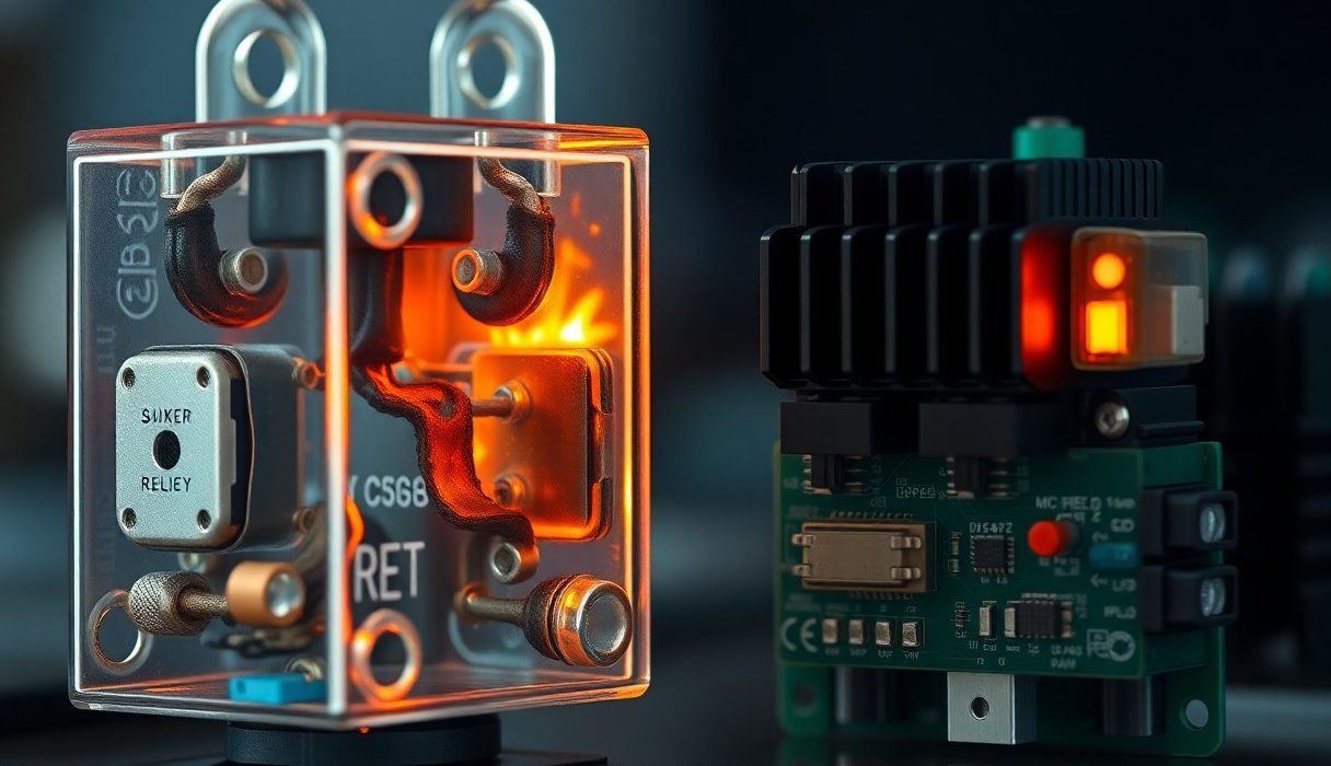
You will find that choosing solid state relays gives your systems faster switching, longer lifespan, and silent, contactless operation with no arcing, leading to reduced maintenance and improved reliability. You also gain lower electromagnetic interference and precise control, but be aware of a potential for thermal failure or fail-short behavior that requires proper heat sinking and protection to avoid dangerous outcomes; this guide shows how to apply SSRs safely to maximize benefits for your projects.
Types of Solid State Relays
You’ll encounter several families of Solid State Relays (SSR) built around distinct output elements and control philosophies, each optimized for specific waveforms, voltages, and switching speeds. Manufacturers commonly classify units as Photo-Optical Relays, triac-based AC SSRs, and Voltage-Controlled Relays (MOSFET/IGBT output), with typical ratings spanning from low-power signal isolation (<1 A) up to industrial power modules (tens to hundreds of amps).
Below is a concise breakdown of the main types and their typical use cases and limits, so you can map your application – whether it’s switching 120 V AC heaters, PWM motor drives at 20 kHz, or isolating sensor inputs – to the right SSR topology.
| Type | Key features / Typical ratings |
| Photo-Optical Relays | Galvanic isolation via LED + photodiode/phototriac, isolation 2.5-5 kV, common for signal-level switching and low-noise AC control. |
| Triac-based SSRs | AC-only switching, available with zero-cross or random turn-on, typical ratings 24-600 V AC and 2-40 A; low cost for resistive loads. |
| MOSFET / IGBT (Voltage-Controlled Relays) | DC and AC variants using MOSFET stacks or IGBTs, fast switching (kHz-tens of kHz), low conduction loss, ratings up to 100s of volts and >100 A in power modules. |
| Hybrid / SSR with snubber | Integrated RC snubbers or RC+MOV protection for inductive loads; useful where transient suppression and longevity are required. |
- When you need isolation for control signals, prefer Photo-Optical Relays for their inherent galvanic barrier.
- If you’re switching line AC resistive loads, a triac-based SSR with zero-cross switching often minimizes EMI and inrush stress.
- For PWM, DC switching, or fast-cycle loads choose Voltage-Controlled Relays built from MOSFET or IGBT stacks.
Photo-Optical Relays
You’ll often find Photo-Optical Relays used where isolation and low leakage matter: medical instrumentation, telecom interfaces, and precision measurement systems. Typical designs pair an LED input with a photodiode or phototransistor output and deliver isolation of roughly 2.5-5 kV between input and output; that isolation level protects low-voltage control electronics from high-voltage circuits and ground loops. Performance-wise, expect switching times in the microsecond to millisecond range and leakage currents in the nanoamp to microamp band, which makes them ideal for signal-level switching but less suitable for high-current power switching.
In practical terms, you can deploy photo-optical SSRs to switch logic-level loads or to isolate sensors in harsh EMI environments. Manufacturers such as Avago/ Broadcom and Lite-On specify typical CTR (current transfer ratio) and LED drive current-so you should size the LED drive (often 1-20 mA) to guarantee the required output current. Also note that photo-optical devices degrade with time and temperature, so you should derate for long-term reliability when used near their thermal limits.
Voltage-Controlled Relays
Voltage-controlled SSRs use MOSFET or IGBT output stages that you drive with a control voltage; these excel for DC switching and high-frequency control. You’ll see MOSFET-based SSRs rated commonly from 30-100 V for automotive and battery systems and up to several hundred volts for industrial modules, with continuous currents from a few amps to >100 A when implemented as multi-device power modules. Response times are fast-sub-microsecond gate switching is possible-so you can use them for PWM motor controllers and active power conversion with much lower conduction loss than triac SSRs.
Thermal management becomes the limiting factor for you when using voltage-controlled SSRs: Rds(on) and package thermal resistance determine how much current you can sustainably pass. For example, a MOSFET SSR with Rds(on) = 10 mΩ and 50 A continuous current will dissipate ~25 W, so you’ll need proper heatsinking and possibly derating by 30-50% at elevated ambient temperatures. Pay attention to dV/dt immunity and avalanche ratings too, because fast switching into inductive loads can produce damaging transients.
Design guidance you can apply includes selecting MOSFET stacks with matched thermal coefficients, using current-sharing arrangements in parallel devices, and adding external RC snubbers or TVS diodes for inductive loads; these steps lower failure rates and improve lifetime for high-duty-cycle applications. Assume that
Advantages of Solid State Relays
In industrial and embedded applications you gain measurable performance improvements: switching times commonly range from tens of microseconds to under 1 ms for MOSFET- or IGBT-based SSRs compared with typical mechanical relay operate times of 5-20 ms and contact bounce of 2-5 ms. That faster, repeatable timing lets you implement high-frequency PWM for motor control or precise sequencing without contact wear, and it reduces electromagnetic interference caused by arcing during make/break events.
Moreover, SSRs remove contact degradation and contact resistance variability from your maintenance equation: typical mechanical relays achieve around 10^5-10^7 mechanical operations before performance declines, while properly cooled SSRs are rated at 10^7-10^9 switching cycles. You should, however, select the correct SSR topology-zero-cross AC SSRs, for example, are excellent for resistive loads but will not give you phase-angle dimming or sub-cycle timing precision.
Speed and Responsiveness
When you need tight timing, SSRs deliver predictable edges and minimal jitter; MOSFET-based DC SSRs can switch in microseconds, supporting PWM frequencies in the tens of kilohertz for soft-starts, choppers, or precision current control. In contrast, electromechanical relays introduce variability from spring and contact dynamics, so designs that require repeatable sub-millisecond response almost always favor SSRs.
At the same time, be aware of topology limits: many AC SSRs implement zero-cross switching, which ensures low inrush current and reduced EMI but inherently delays switching until the next mains zero crossing – up to 10 ms on 50 Hz power – making them unsuitable for applications that need immediate or phase-controlled switching. For phase or fast timing you must choose SSRs without zero-cross detection or use MOSFET/IGBT solutions designed for fast gating.
Increased Longevity
Your system uptime improves because SSRs eliminate contact wear, pitting, and oxidation that shorten mechanical relay life; in harsh environments with high switching frequency or corrosive atmospheres, SSRs can extend service intervals dramatically. Manufacturers’ datasheets commonly rate SSRs for orders-of-magnitude more cycles than mechanical relays, but that long life depends on proper thermal management and staying within the device’s SOA (safe operating area).
Failure modes differ: instead of an open-circuit failure seen in worn mechanical contacts, SSRs most often fail by becoming shorted or by gradual parameter drift under thermal stress, so you must design with protective measures such as fusing, current limiting, and diagnostic monitoring. Integrating redundant switching paths or fail-safe interlocks can mitigate the danger of a stuck-on SSR in safety-critical equipment.
On the thermal side, you should size heatsinks and follow derating curves closely: an SSR rated for 25 A at 25 °C case temperature may need to be derated to 10-15 A at 60-75 °C, and on-state voltage drop still produces heat (for example, a 1 V drop at 10 A is 10 W). Calculating P = Vdrop × I and consulting the datasheet thermal resistance lets you choose the correct cooling strategy-passive heatsink, forced air, or PCB mounting-to realize the long-life benefits in your application.
Tips for Selecting Solid State Relays
When you pick an SSR, match the device to both the electrical demands and the thermal environment of your application. Pay attention to voltage and current ratings, type of output device (triac/thyristor vs MOSFET), switching mode (zero-cross vs random turn-on), and control drive voltage. For example, for a 230 VAC resistive heater driven at 20 A you should typically choose an SSR rated at least 40 A and designed for 400-600 VAC to give margin for surges and poor heat-sinking; using smaller margins often leads to overheating and premature failure.
- Match RMS and surge ratings: pick SSRs with surge capability above expected inrush (motors and incandescent loads can be 5-10× steady current).
- Derating and heatsinking: expect to derate current at elevated ambient – many power SSRs require substantial heatsinks to avoid thermal runaway.
- Off-state leakage: review leakage current when the SSR is “off” if you switch low-current or indicator circuits (leakage can be in the μA-mA range and may keep lamps dimly lit).
- Switching mode: use zero-cross SSRs for resistive loads to reduce EMI; use random turn-on or MOSFET-based SSRs for phase-angle control or fast PWM.
- Certifications and safety: verify UL/IEC approvals and insulation ratings if you handle mains or safety circuits.
This practical checklist helps you avoid common mistakes and ensures the Solid State Relay you select delivers safe, reliable operation.
Voltage and Current Ratings
You should verify both continuous RMS voltage and peak/surge capabilities when selecting an SSR. Typical AC SSRs are specified for line voltages from 24 VAC up to 600 VAC; DC/MOSFET SSRs are often rated from 60 V up to several hundred volts. Make a practice of sizing continuous current at least 25-50% above your maximum expected load current-so a 20 A running load normally calls for a 25-30 A minimum SSR, and 35-40 A if you expect frequent duty cycles or high ambient temperatures.
Also account for on-state voltage drop and resulting power dissipation: many AC triac/thyristor SSRs have a forward drop around 1-2 V, so at 30 A you’ll dissipate roughly 30-60 W in the device unless well heat-sunk-this is a common cause of failure if overlooked. For inductive or motor loads include surge ratings and let-through energy (I²t); if inrush is 5-10× steady current, select an SSR with rated surge capacity or add an inrush limiter to protect against overcurrent.
Environmental Considerations
Account for ambient temperature, altitude, humidity, and enclosure airflow when specifying SSRs. Many SSR datasheets require derating above ~25-40 °C; in industrial cabinets at 50-60 °C you may need to reduce allowable current by 30-50% or install forced-air cooling. High altitude reduces convective cooling, so derate further or use larger heatsinks. If you place SSRs in dusty or corrosive atmospheres, choose devices with appropriate IP or use protective enclosures and conformal coating to prevent leakage and tracking.
Vibration and mechanical shock matter when SSRs are mounted on PCBs or thin panels-use screw-mount packages or vibration-rated modules for transportable equipment. Also consider that condensation and repeated thermal cycling accelerate solder joint fatigue and may expose you to electrical hazards from unexpected leakage; specify SSRs and mounting methods tested for your environmental class and include gasketing where needed.
EMI and switching transients are part of the environment you control: for inductive loads add snubbers or RC networks (common starting point 100 Ω / 0.1 μF across the load for AC TRIAC SSRs) and use MOVs or TVS diodes for mains surge protection to limit voltage spikes that can otherwise latch or destroy semiconductor outputs.
Step-by-Step Installation Guide
Installation Steps Overview
| Step | Details |
|---|---|
| 1. Safety Prep | Disconnect power and lock out the supply. Verify with a multimeter that no voltage is present before touching terminals; high-voltage circuits can be lethal. |
| 2. Select SSR & Heatsink | Match SSR rating to load current and voltage (example: 25 A SSR for loads up to 25 A). Expect a 1-2 V drop across the SSR-at 20 A that becomes ~30 W of heat, so size the heatsink accordingly. |
| 3. Mounting | Use thermal compound or an insulating pad as required by the SSR. Secure with recommended hardware and ensure good thermal contact to keep junction temperature within spec. |
| 4. Control Wiring | Use 22-16 AWG for control wiring (many DC-input SSRs accept 3-32 V DC). Observe polarity on DC inputs and verify input LED functions before load tests. |
| 5. Load Wiring | Run load conductors in the correct terminal order; typical practice is series wiring with SSR on the hot line for AC, or in-line for DC loads. Use 14-10 AWG depending on current, and fit properly sized fuses or breakers at ≈1.25× full-load current. |
| 6. Grounding & Insulation | Bond enclosures and heatsinks to earth ground when required. Keep control and power wiring separated to minimize interference. |
| 7. Test | Perform no-load verification, check terminal torque, then apply power and verify switching behavior with the intended control signal. |
Tools Required
You should have a digital multimeter, an insulated screwdriver set, wire strippers and a quality crimping tool. Include a torque driver capable of low-torque settings (typical terminal specs are in the 0.4-0.8 N·m range for many SSRs); improper torque leads to poor contact and heating.
Keep thermal paste or an insulating thermal pad, appropriate mounting hardware, a heatsink, and safety gear-insulated gloves and eye protection-on hand. Choose wire sizes by current: control wiring 22-16 AWG, power/load wiring 14-10 AWG for currents from 10-30 A respectively.
Wiring Instructions
Start by confirming the SSR type (AC or DC output) and the control-input range; many DC-input SSRs accept 3-32 V DC and will show an LED when driven. You must wire the SSR in series with the load: for AC systems place the SSR in the hot conductor, and for DC loads place it in the positive feed. Always include a properly rated fuse or breaker upstream sized to ~1.25× the expected load current to protect both wiring and the SSR.
Terminate conductors with insulated lugs for high-current runs and torque terminal screws to the manufacturer’s specification. Keep control wiring physically separate from power cables to reduce electromagnetic interference, and verify input polarity on DC-control SSRs before applying voltage; reversing polarity can prevent operation or damage the input stage.
Before applying full load, perform a bench or no-load test: energize the control input and confirm the SSR indicator and the absence of abnormal heating. For inductive or highly capacitive loads, select an SSR rated for that load type or add appropriate snubber/RC networks-mismatched SSRs can fail prematurely under high dV/dt or inrush conditions.
Factors to Consider When Choosing
You must weigh electrical ratings, switching behavior, and thermal limits against the demands of your system: specify the voltage rating and current rating with margins (typical practice is 25-50% derating for continuous loads), check leakage current and on-state voltage drop for standby losses, and confirm the SSR’s thermal resistance (°C/W) to size heatsinking properly. Practical examples: a 25 A, 240 VAC SSR with Rth(j‑c)=0.8°C/W will run significantly hotter than a 10 A device under identical dissipation, and a motor controller with 6-8× inrush requires an SSR with higher surge capability or a soft-start circuit.
- Voltage rating – steady-state and transient tolerances
- Current rating – continuous and surge/inrush
- Switching type – zero-cross vs random fire
- Thermal management – Rth, heatsink size, ambient
- Protection features – snubber, dv/dt, overtemp
Thou, prioritize matching thermal management and derating to ensure long-term reliability.
| Factor | Design consideration / typical value |
| Voltage Rating | Choose >25% above nominal; include expected transients |
| Current Rating | Match continuous RMS and specify surge capability (e.g., motor inrush×6-8) |
| Switching Mode | Zero-cross for resistive/lighting, random for phase-control or fast pulsing |
| Thermal Resistance | Specify Rth(j‑c) and compute heatsink to keep junction < 100-125°C |
| Protective Features | dv/dt ratings, snubbers, built-in transient protection |
Application Requirements
You need to document the control interface and duty cycle: specify the control voltage range (for example 3-32 VDC for many SSR inputs), expected switching frequency (Hz or cycles/min), and whether isolation or safety agency approvals (UL/CE) are required. For continuous industrial heaters running 24/7 at 20 A and 240 VAC, you should plan for robust heatsinking and auxiliary cooling; for intermittent OEM signals at 5 A, a PCB-mount SSR with lower thermal mass may suffice.
- Control voltage – input drive range and optoisolation needs
- Switching frequency – affects device heating and lifetime
- Duty cycle – continuous vs intermittent impacts derating
- Safety approvals – UL, VDE, CE where applicable
- Environmental – ambient temp, vibration, humidity
Thou, document every operating parameter so you can choose an SSR with adequate margins.
Load Types
You must distinguish between resistive, inductive, capacitive, and motor loads because each imposes different electrical stress: resistive heaters are straightforward and suit zero-cross SSRs, inductive loads (solenoids, transformers) produce back-EMF and require SSRs with snubbers or external RC networks, and capacitive inrush from LED drivers or filter caps can exceed steady-state ratings by several times. Concrete examples: an LED driver with a 30 A startup spike requires either an SSR rated for that surge or a current-limiting soft-start; a 3 kW heater at 240 VAC draws ~12.5 A RMS and is easily handled by a 25 A SSR with modest heatsinking.
- Resistive – predictable, low dv/dt sensitivity
- Inductive – needs snubbering and high dv/dt tolerance
- Capacitive – watch inrush current and charging spikes
- Motors – high startup torque currents and possible frequency content
- Mixed loads – design for worst-case component
Thou, evaluate inrush and transient behavior first when selecting an SSR for non‑resistive loads.
| Load Type | Selection notes / mitigation |
| Resistive (heaters) | Zero-cross SSRs, derate 25-50% for continuous duty |
| Inductive (coils, transformers) | Use snubbers, choose SSR with high dv/dt and surge ratings |
| Capacitive (LED drivers, filters) | Address charging inrush; consider soft-start or SSRs with surge capability |
| Motors | Select SSRs with high surge rating or use external soft-start/drive |
| Mixed/Variable | Design to worst-case peak and include thermal safeguards |
You should also verify switching topology: for AC phase-angle dimming use random‑fire SSRs rated for high dv/dt and include EMI suppression; for DC switching use MOSFET-based SSRs with known Rds(on) and thermal curves. Include sample calculations (I²R dissipation, heatsink sizing) in your specification to remove ambiguity for suppliers. Thou, ensure test cycles replicate expected field conditions before finalizing the SSR choice.
- Switching topology – zero-cross vs random vs MOSFET DC
- Inrush handling – surge rating, soft-start options
- EMI/EMC – filtering for phase-angle control
- Thermal design – perform I²R and Rth calculations
- Field validation – bench test with representative load profiles
Thou, validate SSR selection with worst-case load tests and thermal measurements.
Pros and Cons of Solid State Relays
| Pros | Cons |
|---|---|
| Silent operation and no mechanical wear, enabling >10^8 switching cycles in many designs. | Off-state leakage typically 1-5 mA (varies by model), which can keep sensitive loads partially energized. |
| Very fast switching – microseconds to milliseconds depending on output device – ideal for PWM and tight control loops. | On-state voltage drop (e.g., 0.7-2.0 V) causes heat dissipation that requires heatsinking and thermal derating. |
| No contact bounce, improving repeatable timing and reducing EMI from arcing on contact transitions. | Limited surge and inrush handling vs mechanical contacts; brief surge ratings (tens to hundreds of amps) can be exceeded by motor or transformer inrush. |
| Compact, low-mass packages free up panel space and reduce installation complexity for high-channel-count systems. | Failure modes tend to be fail‑short in catastrophic events, which can be more hazardous than a fail‑open contact. |
| Low control current and simple drive circuits (often 5-20 mA input LED drive or logic-level MOSFET drivers). | Triac-based AC SSRs require zero-cross switching and can struggle with highly inductive or phase-angle control applications. |
| High reliability in dirty, vibrating environments since there are no moving parts to foul or stick. | Some SSR types introduce higher on-resistance and thermal coupling to the PCB, complicating thermal layout. |
| Predictable, repeatable electrical characteristics useful for automated process control (temperature, flow, etc.). | Higher unit cost for high-current or specially ruggedized SSRs compared with simple mechanical relays in low-duty applications. |
Benefits Over Mechanical
You gain measurable lifecycle and maintenance advantages when you replace mechanical relays with SSRs: field reports show controllers using SSRs for heater control moved from quarterly contact replacement to multi-year maintenance cycles, reflecting >10^8 switching events versus ~10^5 for typical electromechanical relays. Because SSRs switch in microseconds to milliseconds, your PID loops and PWM schemes can run with finer resolution, reducing temperature overshoot and improving process stability.
Thermal systems, ovens, and semiconductor tools benefit particularly: in one industrial oven retrofit, switching to zero-cross SSRs reduced EMI and eliminated contact welding, improving uptime from 98.5% to 99.9% and lowering spare-part inventory. You also decrease EMC headaches since SSRs eliminate arcing and contact bounce; in tight control cabinets where space and noise are constraints, the compact, silent SSRs let you pack more channels per rack and simplify wiring.
Potential Drawbacks
When you use SSRs you must address thermal and leakage behaviors that mechanical relays don’t exhibit. For example, an SSR with a 1.2 V on-state drop at 20 A will dissipate 24 W – forcing you to specify a heatsink with appropriate thermal resistance (often 0.5-2.0 °C/W) and to derate operation above 25-40 °C ambient. Additionally, off-state leakage of a few milliamps can prevent solenoids or pilot loads from fully releasing, a failure mode experienced on packaging lines where SSRs initially replaced mechanical relays and caused partial valve actuation until bleed resistors were added.
You should also consider surge and inductive load limits: motors and transformers produce inrush currents that can exceed the SSR’s non-repetitive surge rating, and triac-based SSRs struggle with phase-angle control or highly inductive loads without snubbers or specially rated devices. In safety-critical circuits, the fact that SSRs can fail short means you must design protective measures (redundant switching, current sensing, fusing) where a mechanical open-circuit failure would otherwise be acceptable.
Mitigation strategies you can apply include choosing SSRs with specified non-repetitive surge currents or MOSFET outputs for DC and AC applications, adding RC snubbers or bleed resistors to handle leakage, ensuring proper heatsinking and thermal monitoring, and using hybrid relays (mechanical contact in series with SSR) where both low leakage and high switching speed are required; these practical steps reduce the risks while preserving the SSRs’ operational benefits.