This guide shows how PhotoMOS solid-state relays and electromechanical relays differ so you can choose the right switch for your design: PhotoMOS offers no mechanical wear, fast switching, and low contact bounce, while electromechanical relays provide higher voltage/current handling and clear galvanic isolation; however, be aware of contact arcing and mechanical failure risks with electromechanical devices, and consider leakage and thermal limits when using PhotoMOS in safety-critical circuits.
Types of Relays
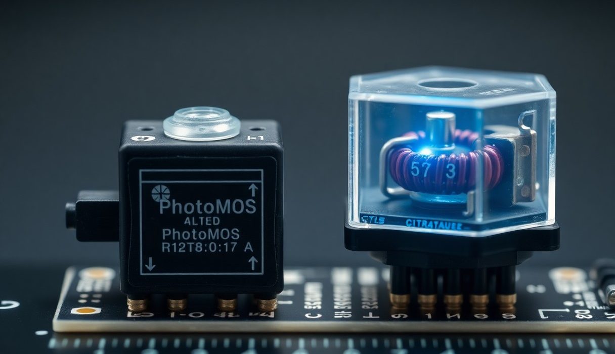
You encounter two dominant relay families in designs: solid-state PhotoMOS relays and traditional electromechanical relays. You’ll favor PhotoMOS when you need very high cycle life (>10^8-10^9 operations), fast switching (microseconds to low milliseconds), and immunity to contact bounce; conversely, you’ll pick electromechanical types for high inrush or steady currents (typical contact ratings 5-30 A, surge peaks up to 100-200 A) and the lowest possible on-contact resistance.
When comparing them side by side you must account for specs like off-state leakage (PhotoMOS: ~0.1-100 µA depending on model), on-resistance (PhotoMOS: ~0.1-5 Ω typical; electromechanical: milliohms), switching time (PhotoMOS: <1 ms common; EMR: 5-20 ms), and life expectancy (EMR: ~10^5-10^7 mechanical cycles). Example: a Panasonic PhotoMOS rated 2 A with R_on ≈ 1-2 Ω works well in low-current signal isolation, while an Omron SPDT power relay rated 10 A handles motor loads but introduces contact bounce and wear.
- PhotoMOS
- Electromechanical relay
- Off-state leakage
- On-resistance / contact resistance
- Switching speed & lifetime
| Characteristic | PhotoMOS vs Electromechanical |
| Switching mechanism | Solid-state (MOSFET/photodiode) vs mechanical contacts (armature/contact) |
| Typical switching speed | Microseconds-milliseconds (PhotoMOS) vs 5-20 ms (EMR) |
| Lifetime | 10^8-10^9 cycles (PhotoMOS) vs 10^5-10^7 cycles (EMR) |
| Current/voltage handling | PhotoMOS: usually ≤10 A and limited voltage; EMR: tens of amps and higher AC voltage capability |
| Failure modes & risks | PhotoMOS: thermal stress, increased R_on, leakage; EMR: contact wear, arcing/welding, bounce |
Overview of PhotoMOS Relays
You’ll find PhotoMOS relays use an LED-driven photodiode to control MOSFETs inside a hermetic package, giving you galvanic isolation typically in the 1.5-4 kVrms range depending on part. Manufacturers like Panasonic and Toshiba publish parts that switch DC and AC at low currents (0.5-5 A ranges common) with R_on from fractions of an ohm to several ohms; their lack of moving parts yields silent switching and cycle lives measured in hundreds of millions to billions of operations, which benefits high-frequency switching and telecom or instrumentation applications.
In practice you must trade off the benefit of no contact bounce against limitations: PhotoMOS devices show measurable off-state leakage (from sub-microamp to tens of microamps) and dissipate heat according to I^2R_on, so thermal derating is important-expect derating at elevated ambient temperatures and near the device’s max DC load. For low-voltage signal isolation, precise multiplexing, or where EMI from contact arcing is unacceptable, PhotoMOS is often the better fit.
Overview of Electromechanical Relays
You should regard electromechanical relays as the go-to when you need very low contact resistance and high current capacity; standard SPDT/DPDT formats can switch 5-30 A continuously and tolerate short surge currents far above steady ratings. Their switching action is visible and measurable: pull-in times often 5-15 ms, release times similar, and contact bounce lasting several milliseconds-this matters when you design debounce circuits or snubbers for inductive loads.
Practical deployments show EMRs excel in power distribution, motor control, and mains switching because contacts can handle AC zero-crossing and arc quenching differently than semiconductors; for instance, a power relay rated 20 A at 250 VAC will typically survive inductive loads with a properly specified arc suppression network, while a PhotoMOS of similar nominal current would overheat. You must also plan for mechanical wear and periodic replacement in high-cycle settings, and for contact protection when switching inductive or dirty loads.
Perceiving how contact materials (silver alloys, gold plating for low-voltage signals) and contact architecture (form A/B, make-before-break vs break-before-make) affect life and performance lets you match relay type, coil drive, and suppression components to your system’s electrical and maintenance constraints.
Key Differences
When you compare the two technologies side‑by‑side, a few measurable distinctions stand out: PhotoMOS relays switch in the microsecond-to-millisecond range and routinely achieve >10^8 cycles, whereas electromechanical relays (EMRs) typically take 5-20 ms to operate and are rated for roughly 10^5-10^7 mechanical operations. You should weigh switching speed, expected cycle count, and the type of load – signal-level multiplexing or low-voltage instrumentation favors PhotoMOS, while mains or high-inrush AC loads usually point toward EMRs.
In practice, you’ll also trade off on-resistance and leakage versus absolute isolation and surge capability: PhotoMOS devices present higher on-resistance (often fractions to a few ohms) and measurable off‑state leakage (µA range), requiring thermal budgeting for continuous currents; EMR contacts give near-zero off leakage and milliohm contact resistance but are susceptible to contact bounce, arcing, and welding under inductive stress. These concrete numbers drive selection for applications such as precision ADC input switching (PhotoMOS) versus motor starter or mains relay banks (EMR).
Operating Principles
PhotoMOS relays use an LED-driven optocoupler that activates internal MOSFETs or MOSFET arrays on the output side, so you get solid‑state switching with no moving parts. Typical LED drive currents lie in the low‑mA range (for example, 1-20 mA), and the output topology can be configured as single‑pole or bidirectional FET stacks to handle AC; switching times commonly fall in the 10 µs to a few ms window depending on device capacitance and gate drive design.
Electromechanical relays rely on a coil, armature, and physical contacts: when you apply coil current (often tens to hundreds of mA depending on coil voltage), the magnetic force closes contacts and completes the circuit. As a result you must manage contact bounce (typically 1-15 ms), mechanical wear, and the need for coil suppression (flyback diode or snubber) to protect your driver and prevent EMI when the coil is de‑energized.
Performance Characteristics
For throughput and longevity, PhotoMOS devices excel: you will see very fast switching, near‑instantaneous repeatability, and lifetimes measured in hundreds of millions to billions of cycles, which is ideal for high‑frequency signal routing or automated test equipment. Conversely, EMRs offer superior current and surge handling – many signal relays are rated for a few amps while power relays handle tens of amps and are often specified for mains voltages – but their mechanical nature imposes finite lifecycle and slower response.
Digging deeper, you should note thermal and safety behaviors: PhotoMOS units dissipate P = I^2·R(on) internally, so 1 A through a 1 Ω FET equals ~1 W of heat you must manage, and their off‑state leakage (commonly in the µA to tens of µA range depending on package) can corrupt high‑impedance measurements. By contrast, EMR contacts can produce arcing and weld on inductive loads – this is the primary operational hazard when switching motors, solenoids, or transformers – so you’ll often add snubbers, RC networks, or arc suppression to protect contacts and extend life.
Pros and Cons
| Pros | Cons |
|---|---|
| You get fast switching (typically tens to hundreds of µs) useful for multiplexing and DAQ. | You face higher on-resistance and voltage drop with many PhotoMOS devices compared to metal contacts. |
| You benefit from long lifetimes (solid‑state PhotoMOS often >10^8-10^9 operations) with virtually no wear. | You must manage contact wear and limited mechanical life with EM relays (typically 10^5-10^7 operations depending on load). |
| You avoid contact bounce and EMI from arcing when using PhotoMOS relays, simplifying signal integrity. | You accept contact bounce, arcing, and potential welding when switching high-voltage or inductive loads with EM relays. |
| You can use PhotoMOS for compact, low-profile PCB mounting (SMD options) to save board space. | You may need larger packages and higher coil drive current for EM relays, increasing PCB area and power draw. |
| You get galvanic isolation of 1.5-5 kVrms in many PhotoMOS parts, useful in medical and test equipment. | You encounter higher on-state losses and heat dissipation in PhotoMOS at high currents, limiting use above ~1-8 A. |
| You find EM relays cheaper and better for high-current and high-voltage switching (10 A-100s A, mains applications). | You deal with slower switching (typically 5-20 ms) with EM relays, which is unsuitable for fast digital multiplexing. |
| You reduce maintenance and eliminate contact cleaning when you choose solid‑state PhotoMOS devices. | You accept the need for suppression networks (snubbers, MOVs, RC) and filter design when using EM relays on inductive loads. |
| You can design quieter systems (acoustic silence) with PhotoMOS relays for consumer or medical gear. | You must plan for thermal management of PhotoMOS under continuous high-current duty due to R_on losses. |
Advantages of PhotoMOS Relays
You gain no-contact, wear-free switching, which gives you extremely long operational life-many PhotoMOS parts are specified for >10^8-10^9 switching cycles-so in high-cycle automated test or data-acquisition gear you drastically reduce downtime and maintenance. Typical isolation ratings range from about 1.5 kVrms up to 5 kVrms, letting you handle low‑level signal isolation and patient-connected medical circuits without bulky relays.
In practice you get very low EMI and no contact bounce, with switching times often in the tens to hundreds of microseconds, so PhotoMOS devices are ideal for fast multiplexers, precision analog routing, and low-current signal paths. Be aware that R_on and leakage current vary by series-many compact PhotoMOS parts are rated for 0.5-2 A, while specialized power variants can approach 5-8 A, so you should match part selection to your current and thermal budget.
Advantages of Electromechanical Relays
You can switch substantially higher currents and mains voltages with EM relays-common PCB power relays handle 5-30 A and larger power contactors go much higher-while exhibiting near‑zero contact voltage drop when closed, which is important for power distribution, motor starters, and HVAC systems. Coil drive is straightforward, and in many cases a simple transistor or driver IC is all you need to actuate the relay.
Deployment in real-world systems benefits from EM relays’ ability to handle large inrush currents and harsh environments; for example, you can reliably switch incandescent lamp loads or motor inductive loads with appropriate suppression, and you often pay less per contact ampere than with high-power solid‑state alternatives.
Operationally you should expect mechanical life on the order of 10^5-10^7 cycles under load, and plan for contact maintenance or replacement in continuous-duty, high-cycle installations; additionally you will need snubbers or RC/MOV networks to prevent arcing and extend contact life when switching inductive or mains loads.
Factors to Consider
When you evaluate PhotoMOS versus electromechanical relays, focus on measurable trade-offs: switching speed (PhotoMOS typically 10-300 µs vs EMR ~5-20 ms), continuous current capability (many PhotoMOS parts are rated for ~0.5-2 A and 60-150 V, whereas EMRs routinely handle 1-30 A at mains voltages), and off-state leakage (solid-state relays have µA-mA leakage that can affect high-impedance circuits). You should also weigh lifetime: PhotoMOS parts can reach >10^9 cycles in signal applications, while EMRs often specify mechanical life from 10^5 to 10^7 operations depending on load and contact material.
Operational failures differ and should influence your choice: contact welding and pitting are a real risk on EMRs when switching inductive loads or high inrush currents, while leakage current and thermal derating limit PhotoMOS use in precision analog or high-power paths. Cost, board area, and drive requirements also matter – PhotoMOS devices typically save space and require only a logic-level LED drive, while EMRs may need driver coils and flyback suppression on inductive loads.
- Switching speed – PhotoMOS for multiplexing/DAQ, EMR for coarse power switching
- Voltage and current ratings – pick EMR for >5-10 A or mains-level switching
- Leakage current – impacts ADC front-ends and sample-and-hold circuits
- Lifetime and cycles – solid-state for high-cycle applications, EMR for fewer cycles but higher surge tolerance
- Environmental robustness – vibration, shock, humidity affect contacts more than semiconductors
- Safety and isolation – creepage/clearance and breakdown voltage requirements may push you to a specific technology
Application Requirements
If your design is a precision multiplexer, instrument front end, or high-channel-count DAQ, you’ll favor PhotoMOS because of its fast switching and long cycle life; for example, switching 64 analog channels at 10 kHz sampling per channel benefits from µs-level switching to minimize settling time. Conversely, when you need to switch motors, heaters, or mains loads with steady currents above a few amps, you’ll typically choose an electromechanical relay for its low on-resistance and ability to handle high inrush currents without excessive heating.
You also need to define signal type and accuracy: if you’re switching low-voltage, low-current sensor lines, PhotoMOS leakage and on-resistance variation across temperature matter; when switching AC mains or inductive loads, specify contact materials, arc suppression, and life-cycle tests for EMRs. In safety‑critical systems, plan for redundant switching or use relays that meet the necessary isolation and regulatory ratings.
Environmental Conditions
For harsh environments – wide temperature swings, high vibration, or corrosion – you must compare package sealing and qualification. PhotoMOS devices generally tolerate vibration and shock better because there are no moving parts, and many are rated from -40 °C to +85 °C, but semiconductor parameters will drift with temperature and derate current. Electromechanical relays can be specified in sealed or gas-filled packages and are often available with higher surge tolerance, but contact life shortens under high humidity, salt spray, or heavy mechanical vibration.
Also consider altitude, UV exposure, and potential for contamination: conformal coatings and hermetic relays mitigate moisture-related contact failures, while solid-state relays avoid contact oxidation altogether. When switching inductive loads in outdoor or industrial settings, include snubbers or RC networks for EMRs to protect contacts, and ensure PhotoMOS parts are rated for repetitive surge currents if used in those roles.
For applications such as automotive telematics or industrial controls where you may see -40 °C to +125 °C, strong shock, or high electromagnetic interference, plan qualification tests (thermal cycling, vibration, salt fog) and choose parts with documented endurance; specify contact protection for EMRs and thermal management for PhotoMOS to prevent accelerated failure modes. Assume that you prioritize the single most limiting factor in your application – be it continuous current, switching speed, or environmental robustness – and select the relay type and part number that explicitly meets those quantified requirements.
Tips for Selection
Match the relay’s electrical ratings to your real-world load: choose a part whose steady-state current rating exceeds your maximum by at least 25% and whose peak or inrush rating covers short bursts (for example, a motor startup might generate 5-10× steady current for 10-50 ms). When you evaluate PhotoMOS devices, check OFF-state leakage (typically nA-µA for many parts, but some high-voltage types can be µA-mA) and ON resistance (often 0.5-2 Ω for low-voltage types), since those affect signal integrity and heating. For Electromechanical Relays, verify contact ratings (e.g., 10 A @ 250 VAC, or 30 A surge) and contact material – silver alloys perform better on low-voltage switching but can oxidize on light loads.
Factor in environmental and lifecycle constraints: specify operating temperature, expected cycles (solid-state parts commonly exceed 10^9 operations; mechanical relays usually rate 10^4-10^7 cycles), and whether silent operation or EMI immunity is important. Use a short checklist when selecting:
- Voltage/current margins (steady and inrush)
- Switching speed and bounce (µs-ms for PhotoMOS, ms for Electromechanical Relays)
- Leakage and isolation requirements
- Thermal derating and PCB layout for heat
- Lifespan (mechanical cycles vs. device MTBF)
Choosing the Right Relay
You should pick PhotoMOS when you need silent, fast switching with high cycle life and when leakage and on-resistance are acceptable for the signal levels involved; typical use cases are low-voltage signal routing, medical signal gating (ECG switches where leakage < 1 µA matters), and telecom line switching. For instance, a PhotoMOS rated 60 V/1 A with Rds(on) ≈ 1 Ω is well-suited for switching logic-level loads and small power rails without mechanical wear.
When your application involves high continuous current, large inductive loads, or mains voltages, select Electromechanical Relays; a 10 A @ 250 VAC SPST relay with silver-cadmium oxide contacts is a common choice for motor controllers and heater loads. You should also favor mechanical relays when you need a galvanic contact that shows near-zero leakage or when a physical open-circuit is required for safety standards and agency approvals.
Common Mistakes to Avoid
One frequent error is underestimating inrush and surge currents: you might spec a relay for 3 A steady-state while the device draws 20 A for 20 ms at startup, which can weld contacts or blow a PhotoMOS by exceeding SOA. Another mistake is ignoring leakage and bus biasing – PhotoMOS leakage can shift thresholds and cause false triggers in ADC front-ends unless you design bias resistors or buffers into the circuit (e.g., 100 kΩ bleed to ground).
Misjudging thermal dissipation is also common: a PhotoMOS with Rds(on) = 1 Ω switching 0.5 A will dissipate 0.25 W and needs PCB copper for heat spreading; an electromechanical relay coil that consumes 200-400 mW can heat nearby components and shorten capacitor life if not spaced properly. Additionally, designers sometimes omit snubbers or TVS diodes on inductive loads, which increases contact erosion and EMI.
To mitigate these issues, test with worst-case loads: run temperature-elevated life tests (e.g., 85 °C for 1,000-10,000 cycles) and include surge testing that replicates motor start or lamp warm-up currents. Use snubber examples such as a 100 Ω + 0.01-0.1 µF RC across inductive loads or a suitable TVS for transient suppression; specify contact protection and select relays with known surge ratings when switching lamps, motors, or capacitive loads. Welding and contact wear are the most dangerous failure modes and should drive your derating strategy.
After you validate the chosen device with in-situ thermal, surge, and lifecycle tests and document margins for leakage, inrush, and ambient temperature, you will have quantified confidence that the selected PhotoMOS or Electromechanical Relays meets your application’s longevity and safety requirements.
Step-by-Step Guide to Implementation
| Step | Details / Example values |
|---|---|
| Specify electrical ratings | Match steady-state current and voltage: for PhotoMOS pick parts with RON low enough that P = I²·RON stays under package dissipation (e.g., for 1 A choose RON ≤ 2 Ω to limit dissipation to ~2 W). For electromechanical relays (EMR) ensure contact rating > your inrush current (many power EMRs handle 10-30 A inrush for motors). |
| Thermal and PCB layout | Allocate copper pour and thermal vias for PhotoMOS heat sinking; follow manufacturer thermal resistance (θJA) – typical small PhotoMOS θJA ≈ 30-60 °C/W. For EMR, allow creepage/clearance and mounting holes; keep coils away from sensitive analog traces to avoid magnetic coupling. |
| Transient protection | Add flyback diodes for DC coils (EMR), and RC snubbers or TVS for inductive loads on both relay types. For switching capacitive loads with PhotoMOS, limit dV/dt per datasheet (often 1-10 V/µs) or add series resistance. |
| Control drive | Drive PhotoMOS LED with appropriate current (typical If 2-20 mA) and include series resistor. For EMR, size driver to provide coil voltage (e.g., 5 V or 12 V) and peak coil current; include transistor or driver IC and back-EMF clamp. |
| Safety & isolation | Verify isolation ratings: PhotoMOS optocouplers frequently provide 1.5-5 kV isolation; EMR coil-to-contact isolation depends on construction. Maintain required PCB creepage/clearance per your safety standard (e.g., IEC 61010 / 60950). |
| Mechanical considerations | Consider lifecycle: PhotoMOS often exceeds 10⁸ cycles; EMR mechanical life commonly 10⁵-10⁷ cycles. Factor vibration and shock-use board locks or chassis mounting for heavy EMRs. |
Installation Process
Start by validating the chosen part against measured worst-case conditions: measure actual inrush currents, ambient temperature, and expected duty cycle. Then, position the PhotoMOS or EMR on the PCB so you maintain manufacturer-specified creepage/clearance distances for mains-level switching; for example, keep ≥8 mm between high-voltage nodes if your design requires reinforced isolation per the datasheet and applicable safety standards. When soldering, follow the package-specific reflow profile for SMD PhotoMOS or use controlled wave/manual soldering for through-hole EMRs to avoid overheating internal plastics.
Next, wire the control circuitry with proper suppression: add a flyback diode (e.g., 1N400x or a fast diode sized to coil current) across DC coils, and fit an RC snubber (e.g., 100 Ω + 100 nF) or TVS across contacts when switching inductive loads. Mount EMRs with mechanical anchors if vibration is expected, and for PhotoMOS ensure you route heat away with thermal vias or a copper area sized per θJA – for example, increase copper area by 2-4× when measured case temperature approaches the part’s maximum under test load.
Testing and Maintenance
Perform initial functional tests: measure on-resistance (or contact resistance) under rated current, verify off-state leakage, and time the switching events. Use an oscilloscope to capture switching transients – PhotoMOS typically switch in tens to hundreds of microseconds, while EMR contact bounce commonly lasts 1-10 ms; log these numbers so you can tune debouncing or timing in firmware. Also run insulation and dielectric tests at the specified voltages (e.g., 1.5-3 kV for basic isolation checks) to confirm isolation integrity after assembly.
For ongoing maintenance, implement a periodic check schedule based on expected cycle count and environment: verify EMR contact resistance and replace relays if resistance increases by >50% or exceeds the datasheet limit, and monitor PhotoMOS case temperature under load – sustained over-temp indicates insufficient cooling or component undersizing. In high-voltage or safety circuits, perform leakage and hipot tests during scheduled servicing to detect developing breakdown paths before they become hazardous.
Finally, watch for failure modes specific to each technology: arcing and contact welding with EMRs under high-current DC switching, and thermal runaway for PhotoMOS if dissipation exceeds package limits – if you detect excessive heating (case temperature rising beyond datasheet by >20 °C during nominal load), de-rate the device or improve thermal management immediately.
To wrap up
So you should weigh PhotoMOS and electromechanical relays by their fundamental performance trade-offs: PhotoMOS provides solid-state, contactless switching with fast response, no contact bounce, long cycle life and low acoustic/EMI emissions-making it well suited for low‑level signals, high‑speed or high‑reliability applications-while electromechanical relays deliver lower on‑resistance, higher current and voltage handling and inherently robust isolation for heavy or inductive loads. PhotoMOS devices bring considerations like leakage current, higher RON and thermal dissipation; electromechanical relays bring contact wear, slower switching and audible/EMI noise, each imposing different driver and protection requirements for your design.
When choosing, match the technology to your load, switching frequency and safety needs: opt for PhotoMOS when you need silent, repeatable, high‑cycle switching of sensitive signals or fast multiplexing, and choose electromechanical relays when switching high power, inductive loads or when maximum galvanic isolation under fault is required. Check the datasheet values that matter to your application-RON, leakage, switching time, life expectancy, drive requirements and thermal limits-so your selection balances performance, cost and longevity for your specific use case.